
Page 55 - MSDN Magazine, May 2017
P. 55
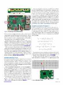
Figure 1 Raspberry Pi 3 Model B with GPIO
Wi-Fi and Bluetooth adapter (9). In the middle of the board, you can see the processor (10) and the network controller (11). On the upper side, you have the General Purpose Input/Output (GPIO) block (12), where you make all connections. Every pin has a differ- ent purpose, as you can see at the top of the figure.
The Raspberry Pi uses two supply tensions: 5V and 3.3V. The black pins are ground and the yellow ones are the GPIO pins that you’ll use in your programming. Note that the pin numbering isn’t ordered. Therefore, unless you have a perfect memory, keep a diagram like that nearby (there’s one available at bit.ly/1WcBUS2).
The second step is to study the kit. I won’t discuss all the content because that can change a lot, depending on the manufacturer (or from what you intend to buy). For this project, you’ll need a bread- board, three LEDs, resistors and wires. To learn more about these components and how to interact with them, see Frank La Vigne’s April 2016 Modern Apps column, “Writing UWP Apps for the Internet of Things,” at msdn.com/magazine/mt694090.
Mounting the First Circuit
Knowing the board and these simple components, you can mount the first circuit. Usually, the “Hello World” for a system like that is a program that makes the LED blink. To make it extra simple, you’ll start by creating a circuit that lights up the LED, without blinking. For that, you don’t need any kind of program, only to understand the circuit you’re going to build.
If you connect the LED directly to the 3.3V pin of the Raspberry Pi, you’d probably burn the LED, as it wouldn’t support the current passing by it. By using Ohm’s law (V = R*I), you need to add a 220 Ω (Red/Red/Black) resistor in the circuit. If you don’t have a 220 Ω resistor available, you can use a larger one–with a larger resistor, there’s less current in the circuit, so the LED isn’t damaged. The resistor can’t be much larger because if the current is too small, the LED doesn’t turn on. In my case, I used a 330 Ω with no problems.
To see what the montage in the breadboard looks like, see Figure 2. The image was created with an open source program called “Fritzing,” which can be downloaded at fritzing.org. msdnmagazine.com
After mounting the circuit (this should be done with the Raspberry Pi power source off to not burn any component), con- nect the power source. If you mounted it correctly, the LED should turn on. If the LED doesn’t turn on, check if you put the poles of the LED correctly—the positive pole (longer wire) and the connection to the 3.3V pin in the Raspberry Pi should be in the same hori- zontal line. The negative pole and the resistor (in this case, there is no polarization) must be in the same line. The second wire of the resistor must be connected to the line that goes to the ground pin in the Raspberry Pi. If everything is right, check if the LED is burned, and replace it with another one. When the LED turns on, you can go to the next step: creating a program that controls the LED.
Installing and Using Windows 10
Until now, you didn’t need an OS because you didn’t need to pro- gram the Raspberry Pi, but you’ll need some programming to go on with your exploration. For that, you’ll use Windows 10. You can download and install Windows 10 for the Raspberry Pi free of cost and, although it isn’t exactly the same version that runs on desktops and tablets, it lets you execute programs for the UWP with no change.
To install Windows 10 on the Raspberry Pi, you must have a compatible micro SD card with at least 8GB.
The first step is to download and install Windows 10 in the SD Card. For that, download and install the Windows 10 Internet of Things (IoT) Core Dashboard tool, located at bit.ly/2lPXrRc.
To install Windows 10 on the Raspberry Pi, you must have a com- patible micro SD card with at least 8GB. Next, select the option “Setup
Figure 2 Mounted Circuit
May 2017 49
